I. Introduction
Two multistage centrifugal pumps can be of the same motor power and number of stages yet give different flow and head. If you only look at the maximum values, or outer size, you may be quoting a model that cannot achieve the real duty point. In this post we’ll describe how a multistage centrifugal pump works, follow the liquid through each stage, show you why pressure increases without multiplying flow, and offer you some practical checks you can run to compare pump structures and confirm a bulk order.

II. What Is a Multistage Centrifugal Pump?
Multistage Centrifugal Pump: A centrifugal pump that has two or more hydraulic stages in series, and through which the liquid flows. The stages are in series, each stage adds head to the same stream of liquid. This contrasts with many complete pumps running together which are usually arranged to increase system flow.

III. What Is a Stage in a Multistage Centrifugal Pump?
A stage is one part of hydraulic energy transfer. It usually includes a rotating impeller and a stationary diffuser or casing passage that conditions the liquid for the next step.
1. Impeller
The impeller gives energy to the liquid from the shaft. The liquid enters at the eye of the impeller and flows outward through the rotating vanes to be discharged with an increased velocity and total head.
2. Diffuser or Volute Passage
The diffuser or volute receives the liquid from the impeller which slows and directs the flow and converts some of the flow velocity into static pressure. The hydraulic design controls how much of the energy in the impeller is transferred to usable pressure.
3. Return Passage
The return path takes liquid from one diffuser to the eye of the next impeller and reduces unwanted swirl. If the interstage guidance is bad, you will have losses, therefore two pumps with the same number of impellers may have different curves and efficiency.
4. First and Final Stage
The suction nozzle delivers liquid to the first stage and the last stage releases pressurised liquid into the discharge casing. The first stage relies on the available inlet pressure and the last casing relies on the total pressure, thus both ends should match the real operating conditions.

IV. How Does a Multistage Centrifugal Pump Work?
A multistage centrifugal pump moves a single stream of liquid through a number of impeller-diffuser stages. This energy transfer continues until the liquid arrives at the discharge.
1. Liquid Reaches the First Impeller
Before starting, the pump and suction line must be filled with a suitable amount of liquid to ensure correct operation of the design. Almost all standard multistage centrifugal pumps will need either a flooded suction or some separate means of priming other than the pump, unless the pump is specifically self-priming or the first stage can survive being fed some air instead of a continuous source of liquid.
2. The Impeller Adds Energy
The motor spins the shaft and the first impeller adds mechanical energy to the liquid, so increasing the velocity and total head of the liquid. Amount added depends upon impeller geometry, diameter, speed, flow rate and internal losses. So stage count doesn’t equal performance.
3. The Diffuser Recovers Pressure
The liquid leaves the impeller and enters the fixed diffuser or casing passage. The passage slows the flow. Some of this energy is converted to static pressure. It is directing the flow to the next stage.
4. The Next Stage Repeats the Process
The liquid is returned from the discharge to the next impeller which adds another increment of head. This is termed series multistage centrifugal pump. The outlet of one hydraulic stage is the inlet of the next stage of the same pump.
5. The Liquid Leaves at Higher Head
This continues until the liquid is sent to the discharge casing in the last stage. The total head developed by a pump is approximately the sum of the contributions of the individual stages, allowing for interstage leakage, clearances, diffuser loss and other hydraulic losses.
V. How Do You Read a Multistage Centrifugal Pump Diagram?
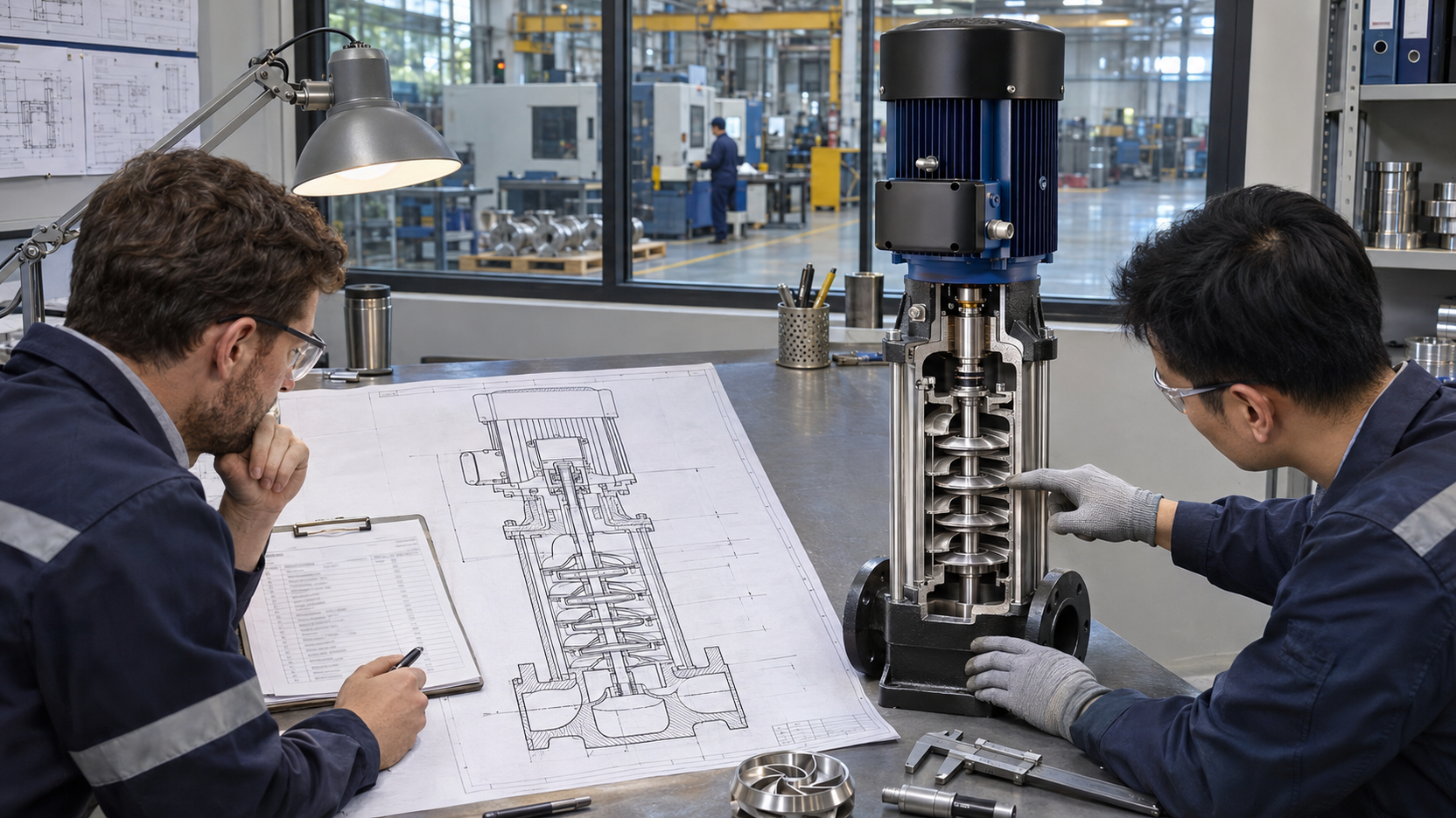
To read a multistage centrifugal pump diagram, follow the liquid from the suction nozzle through each rotating and stationary portion to the discharge. The flow path reveals more about the working principle than the amount of visible parts.
1. Trace the Flow Path
Locate first impeller eye. Trace the liquid out through the impeller, through the diffuser and return passage into the next impeller. See that the drawing displays actual hydraulic stages in series and check the path to the final discharge.
2. Separate Rotating and Stationary Parts
The impellers and shaft spin, while the diffusers, return passages and stage casings stay still. Bearings support the rotor, the shaft seal controls leakage, controlled clearances limit internal recirculation, and the thrust-control system handles the axial force from the impellers.
3. Check What the Diagram Cannot Prove
The essential parts of a multistage centrifugal pump can be illustrated in a diagram, but not flow, head, efficiency, NPSH requirement, pressure rating, materials or service life. Use the diagram for quotation approval. Ask for performance curve, sectional drawing, material list, motor data, connection details and applicable test information.

VI. Why Does a Multistage Pump Increase Head Instead of Flow?
A multistage pump improves head mainly because its hydraulic stages run in series. Each stage passes about the same amount of flow, but adds energy to that flow.
1. Flow Does Not Multiply Across the Stages
If a pump is designed to deliver 10 cubic metres per hour at its duty point then about that flow goes through each stage, you don’t add 10 cubic metres per hour for each impeller. The actual operating flow is determined by the multistage pump curve and the system resistance.
2. Stage Head Adds Along the Flow Path
Each stage raises the head of the liquid, and the contributions of the stages add up to the discharge. So you should compare pumps by head first, and then convert the head to pressure using the real liquid density. For a particular liquid the pressure rise is roughly equal to the liquid density times the gravitational acceleration times the pump head.
3. More Stages Also Increase Design Demands
Increasing the number of stages increases the available head but also affects power, axial thrust, shaft loading, casing pressure, seal pressure and rotor behaviour. When comparing a higher stage version, check the whole curve, motor power, maximum allowable working pressure, thrust-control design, and allowable operating range and don’t assume the only difference is extra stages.
VII. Do Horizontal and Vertical Multistage Centrifugal Pumps Work Differently?
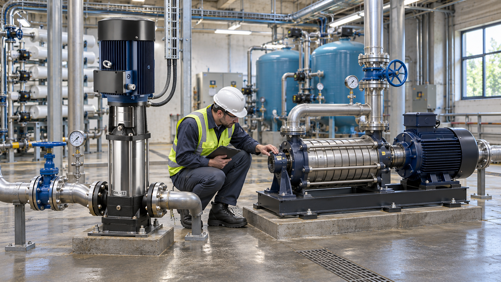
Horizontal and vertical multistage centrifugal pumps operate on the same hydraulic principle, from stage to stage. The main difference between them is the position of the shaft and the mechanical arrangement surrounding the stages.
1. Horizontal Multistage Centrifugal Pump
A horizontal multistage centrifugal pump is one having a horizontal shaft and may have a ring-section, axially split or other casing designs. The core pressure-building principle is not affected by installation and service, although nozzle locations, baseplate alignment, bearing arrangement, seal access and room for removal of stage parts do.
2. Vertical Multistage Centrifugal Pump
A vertical multistage centrifugal pump has a vertical shaft and many clean water designs have stacked chambers with the motor above the pump. The working principle of the vertical multistage centrifugal pump is still the same, but you should check the inlet pressure requirement, priming method, connection layout, seal arrangement and service access for the specific model.
Neither orientation should be considered a performance rating. Compare actual curves at the same flow and head, then select the configuration that will meet the piping, suction conditions, installation space and maintenance plan.
VIII. Where Are Multistage Centrifugal Pumps Used?
Individual practical centrifugal stages are not capable of efficiently producing the required head, so multistage centrifugal pumps are used. The liquid has to be compatible with the internal materials, clearances and diffuser channels as well.
1. Pressure Boosting
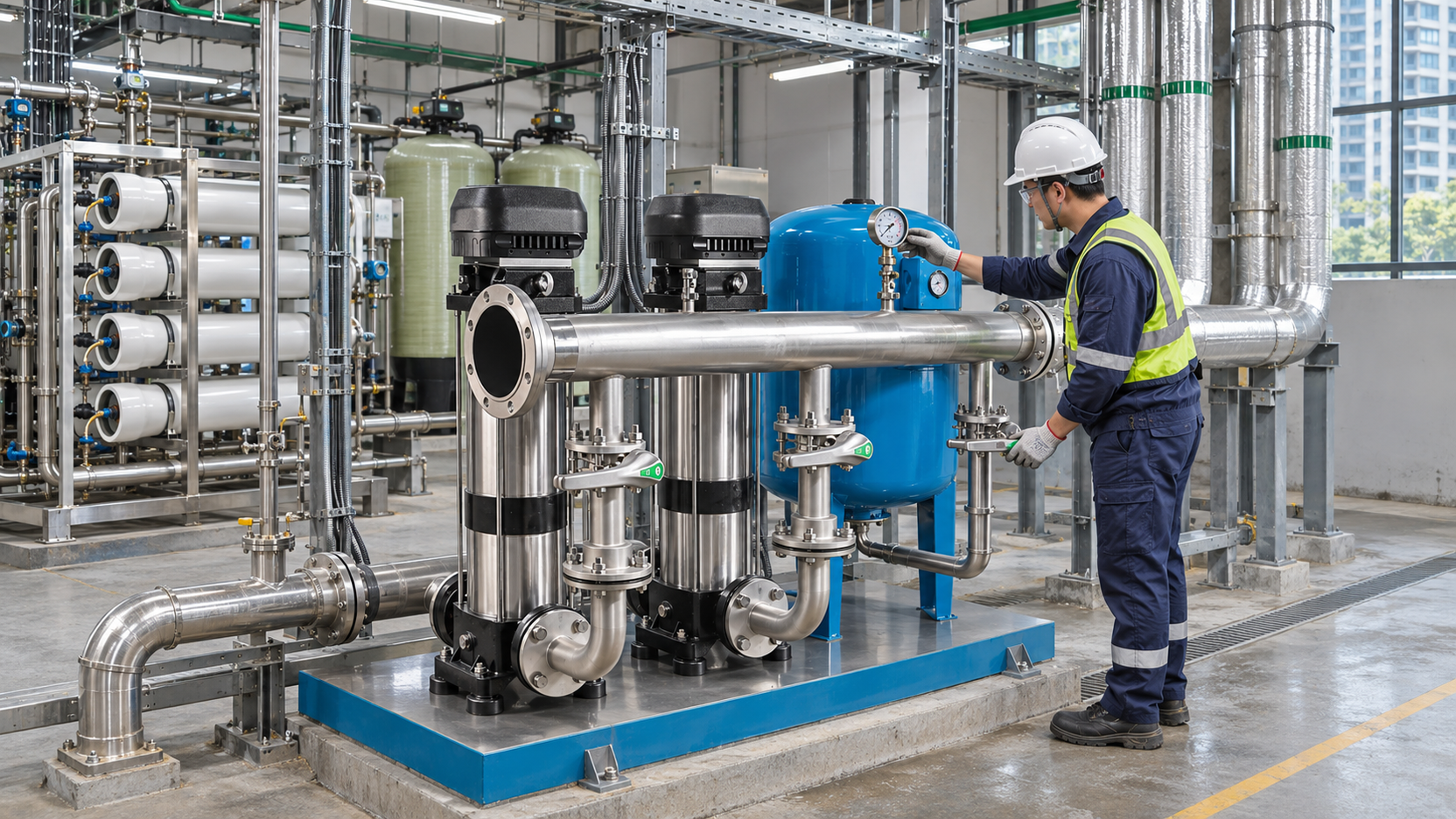
Booster systems for buildings and industry use multistage pumps to overcome elevation, pipe loss and required outlet pressure. Before selection check the simultaneous flow and total head. A high pressure pump cannot compensate for a poor supply.
2. Boiler Feed and High-Pressure Process Supply
Boiler feed and other suitable processes that require a high discharge head at a controlled flow use high pressure multistage centrifugal pumps. Before applying a clean water booster model to this duty, verify the temperature, pressure class, water condition, seal arrangement, minimum-flow need and control method.
3. Reverse Osmosis, Washing, and Water Treatment
A multistage centrifugal pump can be used for reverse-osmosis feed, high-pressure washing and water-treatment systems if its curve and materials are suited to the process. Verify the needed flow at the actual pressure of the membrane or nozzle, as well as the water temperature, filtration, chemical compatibility and seal materials.
4. Long-Distance and High-Lift Transfer
High head may require a multistage centrifugal pump. This may be necessary for long pipes and large elevation changes. Adding extra downstream stages will NOT solve cavitation at the first stage. Check the suction line, available inlet pressure, liquid temperature, and NPSH margin.
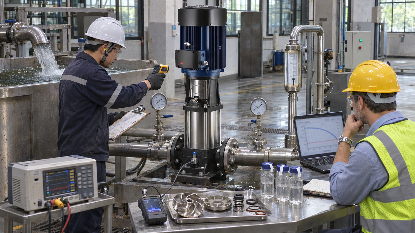
IX. What Should You Verify Before Ordering?
Don’t judge a multistage centrifugal pump by the number of stages or a cutaway drawing; judge it by performance and operating data. Each check should relate the internal working principle to the real system.
1. Confirm the Duty Point
Specify required flow and total head including elevation, pipe and fitting loss, equipment resistance and required outlet pressure. Note separately if the inlet is already pressurised so that the total pressure level may be checked.
2. Check the Complete Pump Curve
Use the curve for the ordered stage count, impeller diameter, speed and frequency. Confirm the rated point, efficiency, input power, motor margin, NPSH requirement and allowable operating range; maximum flow and maximum head are different points, not one promised output.
3. Confirm Inlet Conditions
Compare the available inlet pressure with the required NPSH for the expected flow range. The first stage determines if the rest of the pump gets steady liquid. Include liquid temperature, site elevation, tank level, suction loss, priming method and dry-run prevention.
4. Match Materials and Mechanical Design
Verify the liquid, concentration, temperature, solids, and corrosive components against the casing, impellers, diffusers, shaft, wear parts, elastomers, and mechanical seal. Also check the casing rating, shaft, bearings, axial-thrust control, bolting and seal-pressure limit for higher pressure or stage counts.
5. Verify a Complete Operating Cycle
Approval of sample or bulk order, start-up test, duty point as necessary, input power, efficiency where specified, vibration, noise, leakage, temperature rise, stopping and restarting under recorded conditions. A short test after switching on does not indicate whether the staged hydraulic system reliably supplies the requested flow and head.
X. Conclusion
One stream of liquid is pumped through two or more hydraulic stages in series by a multistage centrifugal pump. Each impeller contributes energy. Each stationary passage recovers pressure and redirects flow. The stage heads build up to the discharge. They do not multiply the flow through each stage.
Use this principle as a standard for comparing pump curves, diagrams, stage arrangements, orientations, inlet requirements, and test results. If you want to buy multistage centrifugal pumps wholesale, for distribution or as an OEM supplier, please submit HunGerät your liquid, required flow and total head, inlet conditions, application, voltage, frequency, target market and planned order quantity. Then we may talk about what hydraulic setup might work for your requirement.
XI. FAQ
1. What Is a Multistage Centrifugal Pump?
Multistage centrifugal pump is a pump in which liquid travels through two or more hydraulic stages in series so that the head added by each stage builds towards discharge.
2. How Does a Multistage Centrifugal Pump Work?
Each impeller adds energy to the liquid, a stationary diffuser turns some velocity into pressure, and a return path feeds the liquid into the next stage until it reaches the final outlet.
3. What Is a Stage in a Pump?
One hydraulic energy-transfer section is a stage, usually an impeller and a stationary diffuser, volute, or return-passage arrangement.
4. Does a Multistage Pump Increase Pressure?
Yes. Each stage adds head to the liquid and the accumulated head produces a higher discharge pressure for a given liquid density.
5. Does a Multistage Pump Increase Flow?
Stages do not multiply flow since they are in series. The flow through each stage is almost equal. The final operating flow is set by the pump curve and the system resistance.
6. Why Are Multistage Centrifugal Pumps Used for High Head?
Several practical impellers can be added in series to increase head, so the pump can achieve a larger total head without a very large impeller or an excessive rotational speed.
7. What Is the Difference Between a Single-Stage and Multistage Centrifugal Pump?
A single-stage pump has one hydraulic stage; a multistage pump has two or more stages in series and is generally selected when the required head is beyond the practical range of a good single-stage model.
8. Do Horizontal and Vertical Multistage Pumps Use the Same Working Principle?
Yes. Both move liquid through successive impellers and stationary passages. Shaft orientation changes the installation and mechanical layout, not the essential hydraulic principle.
9. How Many Impellers Does a Multistage Pump Have?
A multistage pump has at least two impellers. The number required depends on the head developed by each stage and the duty point chosen.
10. Does a Multistage Centrifugal Pump Need Priming?
Most standard designs require that the casing and suction passage be filled with liquid before they will operate, while some special designs are designed to be self-priming.
11. What Are Common Multistage Centrifugal Pump Applications?
Typical applications include pressure boosting, high lift transfer, boiler feed, reverse-osmosis feed, washing and compatible industrial processes.
12. What Are the Main Limitations of a Multistage Centrifugal Pump?
A multistage pump has more internal parts and controlled clearances than a simple single stage pump and so bad intake conditions, solids, wear, internal leakage, axial thrust or operating beyond the specified range can affect performance and reliability.